
Almost all electronic devices incorporate some type of visual indication to provide feedback or to represent their current state. In the most basic form, this may be nothing more than an alphanumeric panel to display the date and time, or in the most complex, the rendering of a movie streamed over the internet and displayed on a high definition screen.
As with all electronic devices and computer systems that evolve over successive generations of technological development, displays too, have become more compact, more energy efficient, and more sophisticated, providing additional and improved features.
While not exactly a recent technology, liquid crystal displays or LCD panels are currently the standard display technology used by a wide range of gadgets and devices. LCDs are very versatile and can be found on electronic watches and clocks, set top boxes, phones, office equipment, scientific and electronic laboratory and field instruments, car dashboards, and LCD televisions and monitors.
The liquid crystal display offers a number of key advantages over its predecessor, the cathode ray tube or CRT display, among them reduced power consumption and compact dimensions. In fact, LCD screens are referred to as flat panel screens compared to the much older and bulkier CRT screens.
That’s not to say that compact CRT displays were not available, however they offered nowhere near the compactness (not to mention the low power consumption) of a LCD panel, and certainly could not have been constructed so small and flat as to be used as the display for a wrist watch.
A Short History of Displays
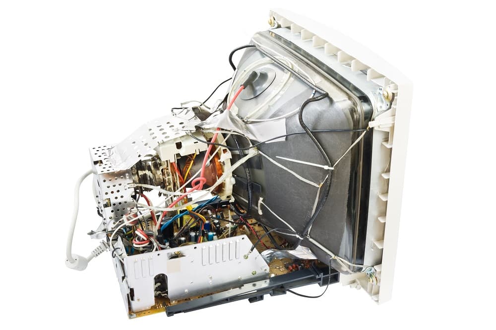
The history of electronic displays starts with the cathode ray tube, which was discovered in the late 19th century, although it wasn’t until 1934 that the first commercially made monochrome CRT TV sets were released by the German manufacturer, Telefunken, and 1954 when color CRTs were used in the mass production of the first color TV sets.
A cathode ray tube is a vacuum tube containing one electron gun in the case of monochrome CRTs, or three electron guns, one each for red, green blue (RGB), in the case of color CRTs. The beam from each electron gun is manipulated with the use of deflection coils in order to scan images onto a phosphorescent screen.
In mid 1960, the plasma video display emerged. Plasma displays were the first of a series of flat panel display technologies to become available. Compared to CRT TVs and monitors, which were quite bulky and required high voltages on the vacuum tube anode (typically 20 kV to 32 kV), plasma displays were significantly more compact, more rugged, could accommodate large screen sizes, with high contrast and brightness.
Plasma displays were succeeded and eventually made obsolete by newer flat panel display technologies, such as the liquid crystal display and organic light emitting diode or OLED display. Today, the versatility of LCD panels makes them the most common type of display in use in electronic equipment and devices.
LCD Technology
The term liquid crystal refers to the state between solid and liquid of a substance. Solids maintain their shape (crystalline lattice), while liquids flow to take on the shape of their container. Liquid crystals are an in-between state where the substance is in a permanent liquid state, but with properties inherent in crystal bodies.
Most liquid crystal display panels use a backlight as a light source, since LCDs do not produce or emit their own light. In essence, an LCD panel works by blocking or allowing this light to pass from the rear of the panel, through several layers of filters and onto the front of the display, eventually making up the image seen on the LCD screen.
The more common types of backlight light sources are:
- cold cathode fluorescent lamps (CCFL)
- hot cathode fluorescent lamps (HCFL)
- electroluminescent panel (ELP)
- external electrode fluorescent lamps (EEFL)
- light emitting diode array (LED)
It is critical that the light from the backlight be distributed over the entire panel. When cold cathode fluorescent lamps (CCFL) are used as the backlight source, a series of optic sheets are applied that help to evenly disperse and diffuse the light. This is very important if a high quality display is expected.
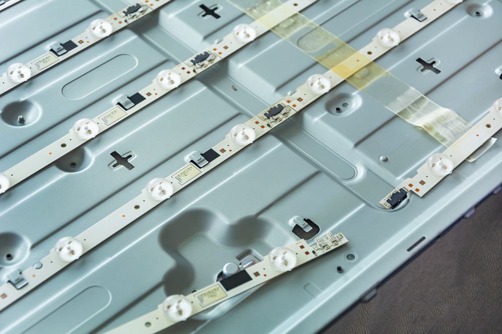
More recent monitors use LED backlighting instead of the more traditional CCFL. LED backlighting offers several advantages over CCFLs. Greater contrast ratio, lower power consumption (and therefore cooler operation), greater reliability, and take up less space making the flat panel even slimmer and lighter.
Next comes the liquid crystal panel itself, comprising two pieces of polarized glass substrate (polarizing film on glass), with the liquid crystal material interposed between them. If the two glass substrates were aligned in the same direction, light would pass right through.
LCDs however, work by aligning the glass substrates perpendicular to each other, causing cross polarization and effectively stopping any light traveling through from the backlight and reaching the front of the display. It becomes the job of the liquid crystals to alter the angle of polarization of the light, so it to can pass through the second glass substrate, rendering the image.
When aligned straight, the liquid crystals have no effect on the light’s polarization and the light continues on, as if no liquid crystals existed. However, liquid crystals can be made to assume a helical or twist position, so that as the light passes through them, it follows this twist and changes its angle of polarization.
To control the amount of twist (and hence the degree of polarization), the liquid crystals are submitted to an electric field or voltage (e.g. through the use of thin film transistors or TFTs). The amount of twist then determines how much light will pass through.
Types of Liquid Crystal Displays
The following table shows the different Twisted Nematic (TN) liquid crystal technologies and their respective characteristics as applied to multi-segment displays. While prevalent in the 1980s and early 1990s, TN liquid crystal technology is still used for small instrumentation panels and can be found in some older monitors.
Nematic refers to the threads or strands of the liquid crystal molecules.
| Display Type | Twisted Nematic (TN) | High Twisted Nematic (HTN) | Super Twisted Nematic (STN) | Film Super Twisted Nematic (FSTN) |
| Advantages | In wide use Easy to produce |
Easy to produce Has a wider viewing angle than TN |
Wide viewing angle Multi-channel drive Can accommodate large amount of display information Good to high contrast |
Wide viewing angle Multi-channel drive Can accommodate large amount of display information High contrast |
| Disadvantages | Low contrast Narrow viewing angle |
Low contrast Narrow viewing angle |
More complicated manufacturing process | More complicated manufacturing process |
| Liquid crystal molecules twist angle | 90 degrees | 110 degrees | 210 - 255 degrees | 210 - 255 degrees |
| Contrast | Acceptable | Good | Better | Best |
| Positive Display | Black on gray background | Black on gray background | Black on yellow and green background | Black on gray background |
| Negative Display | White on gray background | White on gray background | White on blue background | White on gray background |
| Cost | Cheapest | Cheaper | Cheap | High |
For high resolution displays, more recent liquid crystal technologies have been adopted, often incorporating LED backlighting. These newer technologies attempt to overcome some of the drawbacks of TN displays, such as poor color reproduction and narrow viewing angle. They include:
- In-Plane Switching (IPS) – compared to TN displays, offers higher color quality reproduction, stable response times, color accuracy and screen consistency across all viewing angles.
- Plane to Line Switching (PLS) – produced by Samsung, is similar to IPS and offers similar performance to IPS.
- Vertical Alignment (VA) - VA panels offer higher refresh rates than IPS, as well as better color reproduction, higher maximum brightness, and better viewing angles. They have the best contrast ratio of all panel types, but suffer from bad response times, causing blurring with fast-moving pictures.
As stated in the introduction, LCDs are used in devices like electronic clocks and laboratory instrumentation that use multi segment displays, where each segment forms part of an alphanumeric character.
In the case of high definition TVs and computer monitors, thousands of pixels make up the resulting image. Regardless of whether the display is a multi-segment panel or computer monitor, the aim is to turn on only those elements that will render the desired character or image.
On monitors and TVs, pixels are arranged in a matrix formation and constitute the display’s resolution. The higher the display’s resolution, the more pixels available. To reference a pixel, and hence turn it on or off, a two dimensional coordinate addressing scheme is used.
With LCDs, there are two different approaches used to address the coordinate system, referred to as passive matrix addressing and active matrix addressing. Passive matrix addressing uses a grid of vertical and horizontal Indium Tin Oxide (ITO) conductors. To create the desired alignment in the liquid crystals, a voltage difference is applied at the intersecting row and column of a pixel.
To render a complete image, circuitry cycles through the vertical and horizontal conductors in turn, applying the appropriate voltage, until all pixels in the matrix have been addressed. This cycle repeats (known as a refresh cycle), thus rendering the image on the screen.
There are however, some inherent problems with this approach. Because a pixel is refreshed only when its corresponding vertical and horizontal conductors are accessed, it must hold its charge until the next refresh cycle, hence the name passive matrix addressing.
Relying on refresh cycles to maintain the charge means that displays employing passive matrix addressing have a slow response time, as well as reduced contrast (due to an effect known as cross-talk). These problems become more pronounced with higher resolutions, and so passive matrix addressing is not used on displays with more than 240 lines of resolution.
While passive matrix displays may not be suitable for LCD TVs and monitors, they are used in instrumentation and industrial equipment, mainly due to their low cost.
The second approach, active matrix addressing, solves the limitations of passive matrix addressing by assigning a thin film transistor (TFT) and capacitor to each pixel, helping maintain the pixel’s state between refresh cycles.
Where passive matrix displays must access full rows of conductors in order to change the state of pixels, active matrix displays access each pixel directly. This results in significantly faster response times and pixels can change state much more rapidly. The result is that active matrix displays can render rapid moving images with greater clarity.
Furthermore, since active matrix technology provides control over each individual pixel, active matrix displays offer a greater range of contrast, more even brightness, and enhanced color quality across the screen. Because of the superior performance of active matrix technology, today’s LCD TVs, LCD monitors, and laptop screens use active matrix screens.